


 Radiographic Testing (RT):
Radiographic Testing (RT) is a widely used method in the field of non-destructive testing (NDT), designed to reveal internal flaws within materials and welded joints without causing any damage. Unlike surface-level techniques such as Visual Testing (VT), or sound-based approaches like Ultrasonic Testing (UT), radiographic testing relies on X-rays or gamma rays to examine the internal structure of a component.
By capturing images that show internal discontinuities—like cracks, porosity, or inclusions—RT offers a deep, detailed view that is crucial for ensuring safety and quality. This makes it especially valuable in industries where structural integrity is critical, including oil and gas, aerospace, energy, and manufacturing.
✅ An introduction to Radiographic Testing (RT)
✅ The different types of radiation sources used in RT
✅ The inspection process, step by step
✅ How to read and interpret radiographic images
✅ The main advantages and limitations of using RT
Radiographic Testing (RT) is a non-destructive technique that uses high-energy radiation—typically X-rays or gamma rays—to examine the internal features of a material or weld. As the radiation passes through the object, any variation in material thickness or density affects how much radiation reaches the detector. This difference forms an image, revealing hidden flaws like voids, cracks, or inclusions.
To identify internal defects such as cracks, incomplete fusion, porosity, and inclusions
To inspect areas that are inaccessible to surface-based methods
Metals, composite structures, ceramics, and selected polymers
Welding quality control
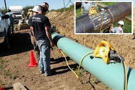
Pipeline inspection and maintenance
Pressure vessel verification
Aircraft parts and turbine blades
Castings and structural components
📌 Note: At NWE, we offer expert oversight and consultancy for RT inspection procedures to ensure they meet safety and quality standards. However, we do not conduct RT scanning ourselves.
RT involves two primary categories of radiation sources:
These naturally emit gamma rays and don’t require electricity, making them ideal for field use.
Iridium-192 (Ir-192): Best for inspecting medium-thickness steel
Cobalt-60 (Co-60): Used for thick-walled components due to its deeper penetration
Cesium-137 (Cs-137): Preferred for materials with lower density
Easily transported for on-site inspection
Effective for thicker materials where X-rays may fall short
Involves handling radioactive materials, demanding stringent safety measures
Produces lower-resolution images compared to X-rays
These machines use electrical energy to generate X-rays, making them more controllable and often safer in controlled environments.
Low-energy tubes: Ideal for electronics or thin metal sheets
High-energy X-ray machines: Suited for dense industrial parts
LINACs (Linear Accelerators): Used for complex, high-precision inspections
Offers high-resolution images for accurate interpretation
No radioactive decay—safer handling compared to gamma sources
Needs a power supply, limiting field mobility
May not penetrate as deeply as gamma rays like Cobalt-60
To ensure clarity and safety, RT is performed through a well-defined sequence:
Clean the surface to remove contaminants
Position the object for optimal exposure and image clarity
Choose between X-ray or gamma ray based on material thickness and setup
Adjust energy output for suitable image contrast and penetration
Use radiographic film or digital detectors to capture internal images
Digital systems provide immediate feedback; films need chemical development
Activate the source to project rays through the material
Internal flaws alter the radiation pattern, forming a detailed shadow image
Interpreters review the image for abnormalities, comparing results to reference charts and standards
Understanding what’s visible on a radiograph is essential for identifying potential defects:
| Image Area | Indicates |
|---|---|
| Dark zones | Low-density flaws: cracks, gas pockets, voids |
| Light regions | Dense, flawless areas |
| Sharp edges | Likely crack or unbonded fusion |
| Blurred variations | Possible inclusions or wall thickness changes |
Pipeline checks: Identifying corrosion, lack of fusion, or wall thinning
Aerospace: Ensuring structural integrity in engine and airframe parts
Weld evaluations: Confirming fusion and filler quality
Detects internal flaws invisible to the naked eye
Suitable for a wide array of materials and shapes
Provides permanent records of the test for future review
High-resolution imaging allows for precise defect evaluation
Compatible with advanced digital imaging systems (DR/CR)
Involves radiation hazards—requires strict safety compliance
Equipment and isotope handling incur high costs
Traditional methods can be time-consuming
Not suitable for very thick objects unless advanced sources are used